Carbon Steel Plain Carbon Steel
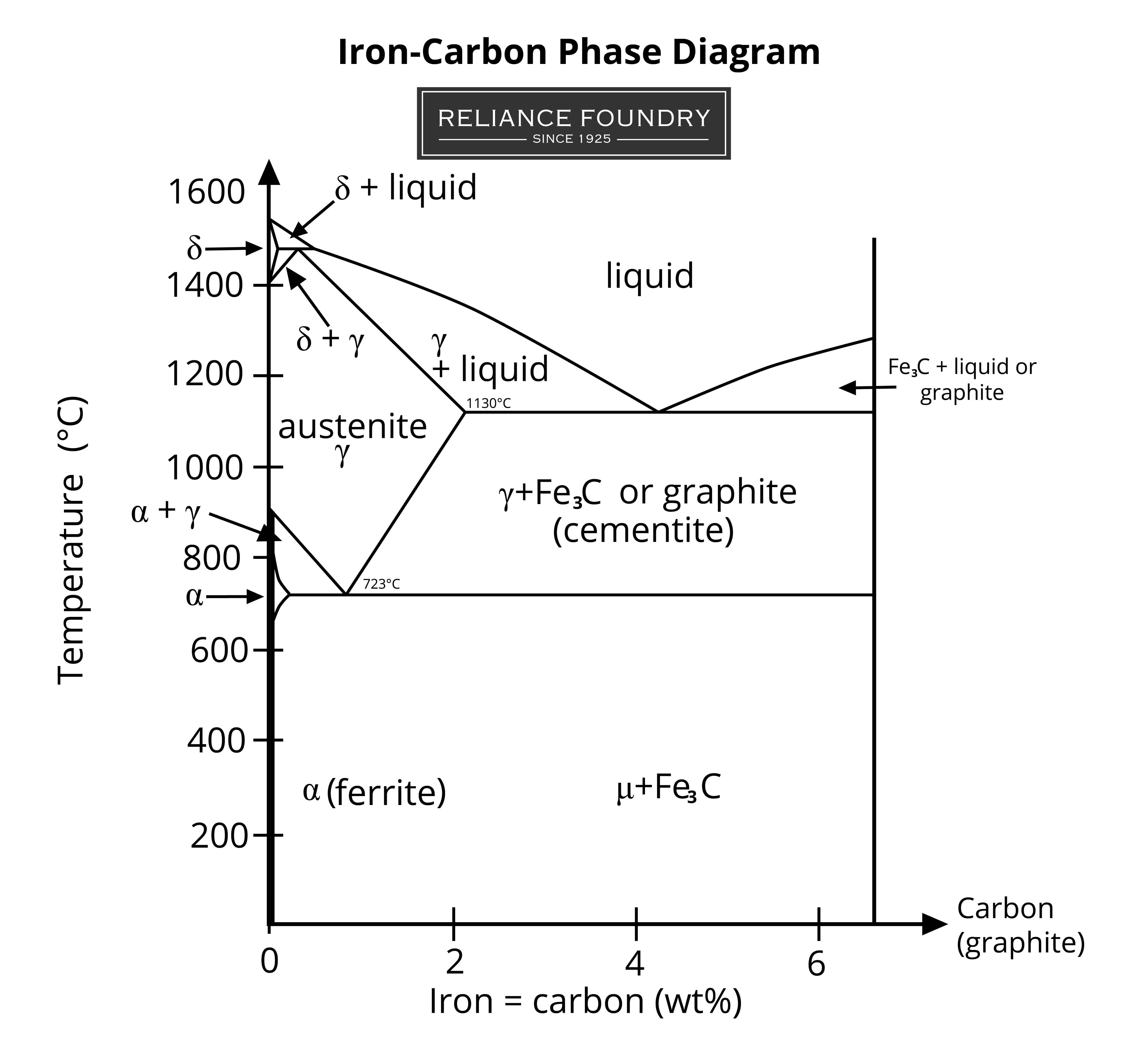
For steels, the stable equilibrium phases include: Ferrite, cementite and austenite. The metastable phases are: Pearlite, bainite and martensite. Phase Diagram of Iron-carbon System In the figure, there is the iron-iron carbide (Fe-Fe3C) phase diagram.

Steel Phase Diagrams 101 Diagrams
Summary of the phase transformations of steel - 07/02/2018 In this article, a summary is given about the phase transformations during solidification and cooling of steel. Iron-Carbon Phase Diagram | Creating | Steel | Cast Iron | hypo-eutectoid | hyper-eutectoid Watch on Introduction
Phase transformations of steels in solidified state (metastable system) tecscience
Want to learn about steel phase diagrams? See our steel metallurgy courses The phases present in an alloy depend on the alloy composition and the thermal treatment to which the alloy has been exposed. Phase diagrams are graphical representations of the phases present in a particular alloy being held at a particular temperature.

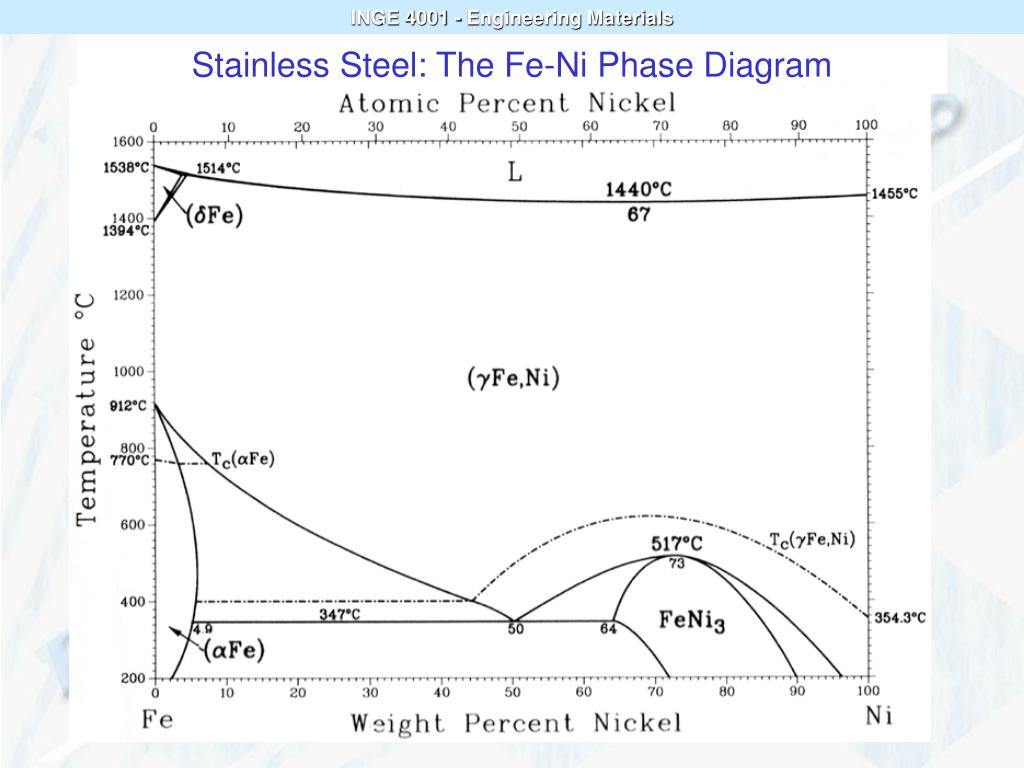
materials engineering Phase diagrams for stainless steels Matter Modeling Stack Exchange
Phase Diagrams. Module 1 • 58 minutes to complete. This course will explore higher-level details about phase diagrams, including the Fe-Fe3C phase diagram. We will use the Fe-Fe3C phase diagram to predict the possible phases and microstructures of a steel alloy based on its composition.
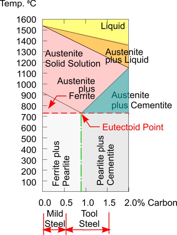
Use the steel phase diagram above. At 600°C
The iron-iron carbide (Fe-Fe 3 C) phase diagram. Below 912 °C, pure iron exists as the alpha phase, ferrite, which has the BCC structure.. carbon steel (pearlite), or cast iron. Carbon is added (about 1% by weight) to iron to make "carbon steel", which is a very hard material. Carbon is rather soluble in the FCC phase of iron, but not.

The steel phase diagram. Download Scientific Diagram
Phase diagrams, also known as constitution diagrams or equilibrium diagrams, graphically represent the influences of alloy composition and temperature on phase changes and solidification. Figure 1
Phase transformations of steels in solidified state (metastable system) tecscience
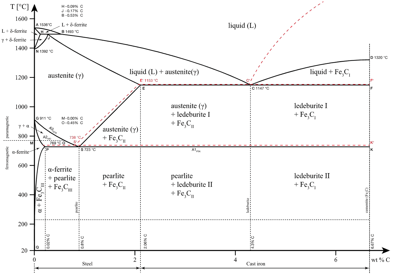
At the highest temperatures, the liquid phase field can be found, and below this are the two-phase fields (liquid + austenite, liquid + cementite, and liquid + delta-ferrite). In heat treating of steels, the liquid phase is always avoided. The steel portion of the Fe-C phase diagram covers the range between 0 and 2.08 wt. % C.
Working the Steel
Figure: Transformation lines in the iron-carbon phase diagram (steel part) Accordingly, three different types of steel can be distinguished, each of which undergo typical microstructural changes during cooling: eutectoid steels with a carbon content of exactly 0.8%! hypereutectoid steels with a carbon content greater than 0.8%!
Phase Diagrams DT Online
Thermodynamics tells us that: Under conditions of a constant temperature and pressure and composition, the direction of any spontaneous change is toward a lower free energy. The state of stable thermodynamic equilibrium is the one with equilibrium minimum free energy. A system at a metastable state is trapped in a local minimum of free
[DIAGRAM] 316 Stainless Steel Phase Diagram
8461 Phase transformations in steels can be compared to those of solid solutions (completely soluble) and crystal mixtures (completely insoluble). The figure below shows steel part of the iron-carbon phase diagram of the metastable system.

Steel Phase Diagrams 101 Diagrams
No phase diagram is more important to materials scientists than the Fe-C phase diagram because it allows us to explain many of the different types of steels..

How to use phase diagrams and the lever rule to understand metal alloys YouTube
The phase diagram illustrates the domains in which particular phases or combinations of phases are stable, and contains information about their equilibrium compositions. Equilibrium phase fractions can also be estimated from a knowledge of the carbon concentration of the steel and an application of the lever rule.

Stainless steel ternary phase diagram
1. Given the Fe-Fe3C phase diagram above, calculate the phases present at the eutectoid composition line at: a. T = 3000ºF b. T = 2200ºF c. T = 1333ºF d. T = 410ºF 2. Calculate the phases in the cast-iron portion of the diagram at the eutectic composition of 4.3% C in combination with 95.7% ferrite at: a. T = 3000ºF b. T = 1670ºF c. T = 1333ºF 3.
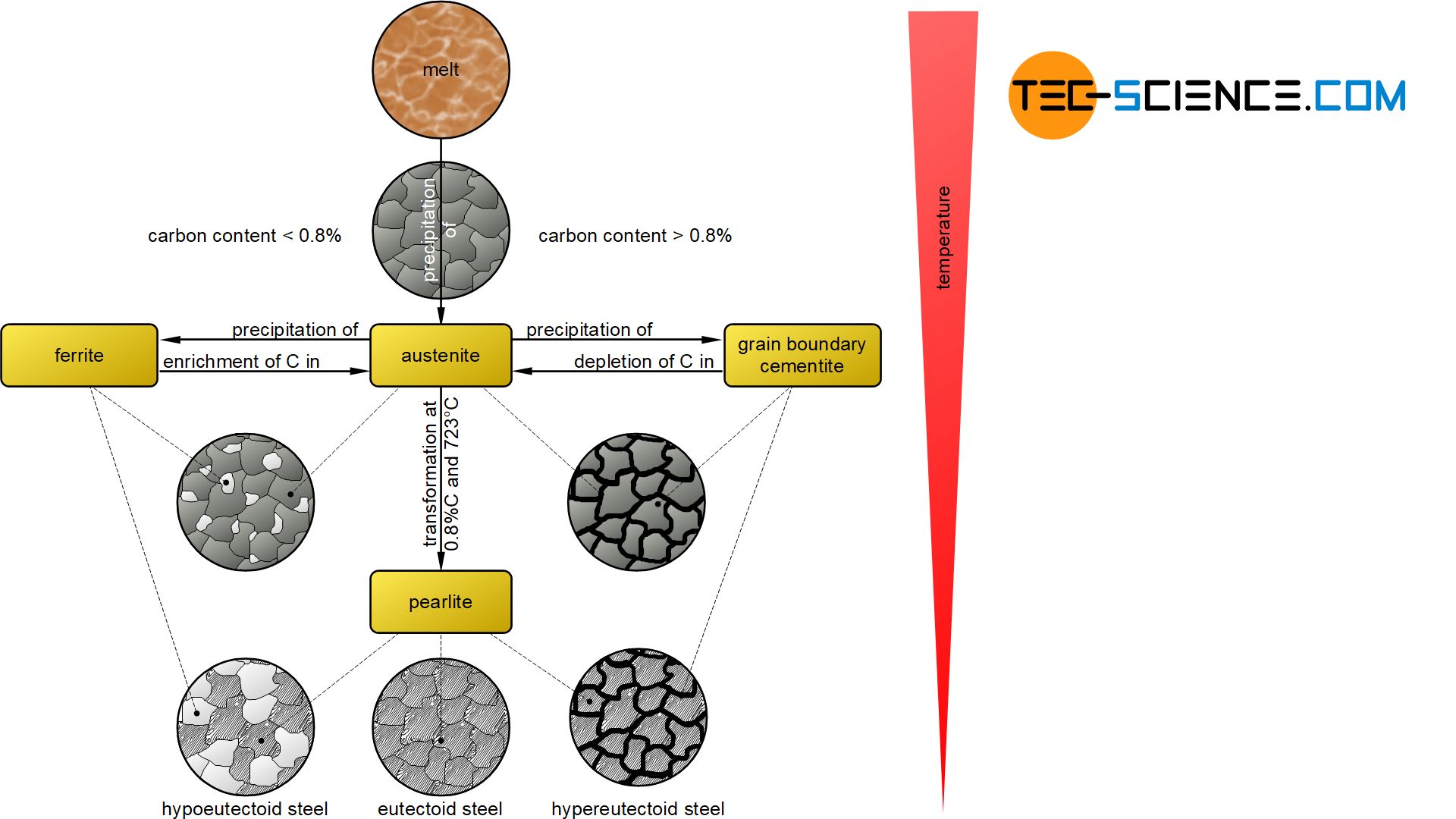
Summary of the phase transformations of steel tecscience
A typical phase diagram. The solid green line shows the behaviour of the for most substances; the dotted green line shows the anomalous behavior of water. The red lines show the and the blue line the , showing how they vary with pressure. The simplest phase diagrams are pressure-temperature diagrams of a single simple substance, such as .

Steel Phase Diagrams 101 Diagrams
The diagram is also known as a "steel phase diagram" since iron alloys are steel. "Steel" is used in place of iron-carbon to show that the diagram is used to understand its microstructure. "Iron-iron carbide phase diagram" is used to represent the iron carbide part of the phase diagram.
[DIAGRAM] 316 Stainless Steel Phase Diagram
For steels, the microstructure and phase fractions in the iron-carbon diagram can be determined using the lever rule. Introduction For many applications it is important to know exactly what microstructure or phase fractions a steel is composed of at a certain carbon content. This ultimately necessitates a calculation.